|
|||||||||||||||||||||||||||||||||||||||||||||||||||||||||||||||||||||||||||||||||||||||||||||||||||||||||||||||||||||||||||||||||||||||||||||||||||||||||||||||||||||||||||||||||||||||||||||||||||||||||||||||||||||||||||||||||||||||||||||||||||||||||||||||||||||||||||||||||||||||||||||||||||||||||||||||||||||||||||||||||||||||||||||
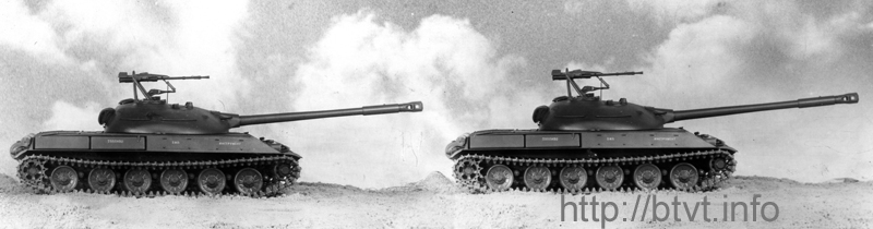
NEW MEDIUM TANK OBJECT
“
Abstract
This material represents a unique historical
and technical source, presenting an English translation of the preliminary
(conceptual) design project of the Soviet medium tank Object “
INTRODUCTION
One of the important principles
adhered to in both domestic and foreign tank design was that the adoption of a
new vehicle into service marked the beginning of development of a new tank
intended to replace it. Even the most advanced design of its time becomes
obsolete within five to ten years.
During the development of each
new-generation tank project, a number of intermediate designs were produced.
Some of them remained at the level of conceptual or technical projects, while
others progressed to the manufacture of running mock-ups. One such example is
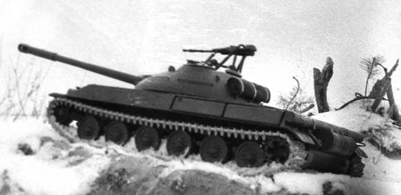
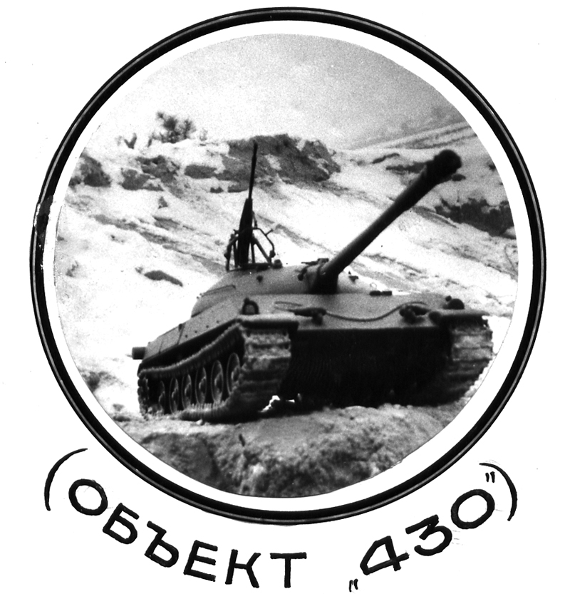
the conceptual design project of the tank Object “
From the diary of A. A. Morozov, 17 December 1952: “The military authorities and the Ministry are urgently preparing tactical and technical requirements for a new medium tank (NMT). A great deal of work is expected, and preparation is required. Our variant of the NMT has received the designation Object ‘430’.” The described project of a new
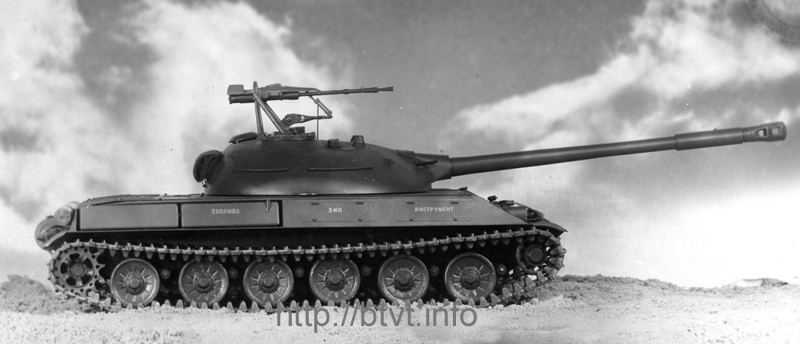
medium tank was developed by Plant No. 75 of the Ministry of Transport and
The project of the new medium tank
was based on the objective of further improving tactical and technical
characteristics in comparison with the Soviet Army’s T-54 medium tank, and on
achieving even greater superiority of domestic armored vehicle technology over
the tanks of foreign armies.
The project of the new medium tank
(Object “
The first variant was developed in
accordance with the tactical and technical requirements proposed to the plant
and is equipped with an 8D12-U engine manufactured by Plant No. 77.
The second variant of the project was developed
with the 4TPD engine produced by Plant No. 77, designed on the basis of
experimental work conducted by NILD and under the direct technical supervision
of Professor A. D. Charomsky.
In both variants, Object “
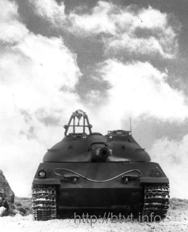
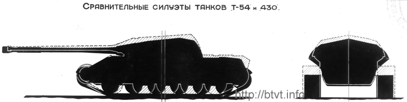
Thanks to a more rational and
compact layout, the width of Object “
At the same time, by increasing the turret ring
diameter from Ø
The narrowing of the hull of Object
“
Installation of the 8D12-U engine
(Ne = 580 hp) and improved transmission efficiency provide Object “
MINISTRY OF TRANSPORT AND
OF THE
NEW
MEDIUM TANK
(Object “
(Object “
CALCULATION
AND EXPLANATORY
MEMORANDUM
TO THE PRELIMINARY
DESIGN
GENERAL STATEMENT
The
present design of a new medium tank has been developed by Plant No. 75 of the
Ministry of Transport and Heavy Machine Building of the USSR, in accordance
with directives and letter No. S-40/00300s dated September 7, 1953, issued by
the Deputy Minister, Comrade Yu. E. Maksarev, as well as additional
requirements outlined in letter No. 700731 dated October 7, 1953, from Deputy
Head of the Technical Directorate of the Ministry, Comrade N. A. Kucherenko,
and Tactical-Technical Requirements of the Scientific-Technical Committee No.
1672040ss dated October 26, 1953.
The fundamental objective of the new
medium tank project is the further enhancement of tactical and technical
characteristics in comparison with the T-54 medium tank of the Soviet Army, and
the achievement of even greater superiority of domestic armored vehicle design
over foreign tank models.
INTRODUCTION
The project of the new medium tank
(Object “
The first variant is designed in
accordance with the proposed tactical-technical requirements, utilizing the 8D12-U
engine manufactured by Plant No. 77.
The second variant incorporates the 4TPD
engine, also developed by Plant No. 77, based on experimental research conducted
by the Scientific Research Laboratory of Diesel Engines, under the direct
technical supervision of Professor A. D. Charomsky.
In both variants, Object “
Due to a denser and more efficient internal
layout, Object “
At the same time, by increasing the turret ring
diameter from
The reduction in hull width, combined with a
fundamental redesign of the suspension and running gear, made it
possible—without exceeding the prescribed combat weight—to significantly
increase armor resistance of both hull and turret by 20–40%, install a stabilized
100-mm D-54 gun with a muzzle velocity of 1015 m/s, and increase the ammunition
load to 55 rounds, which is 20 rounds more than in the T-54.
Installation of the 8D12-U engine (580 hp) and
improved transmission efficiency provides Object “
Fuel stowage totaling
The simplicity of the design of assemblies and
units, combined with their manufacturability, the clarity of external forms,
and the strict internal layout of mechanisms, makes the tank economical to
produce, easy to maintain, and—most importantly — highly powerful both in
firepower and protection.
SECOND VARIANT –
GENERAL CONCEPT
In the second configuration, Object
“
On each side of the engine are identical
transmissions, structurally integrated with the final drives.
This arrangement allowed the volume
of the engine-transmission compartment to be reduced by more than two times—from
The freed internal volume is used to
accommodate additional ammunition and fuel, or may be allocated for other
operational needs.
In this configuration, Object “
TRANSMISSION SCHEME
ADVANTAGES
The adopted transmission scheme significantly
simplifies all mechanisms, thereby increasing reliability and ease of
maintenance.
As a result, the following components are
eliminated:
Simultaneously, 24 dynamic seals requiring
maintenance are eliminated, along with a large number of couplings and
lubrication points.
The system is replaced by two integrated
transmission units, featuring only two seals and a single lubrication filling
point, shared with the final drives and engine, providing high overall
mechanical efficiency.
For example, in 5th gear, engine power is
transmitted directly to the final drive input shaft, with only one pair of
cylindrical gears in operation.
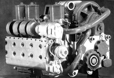
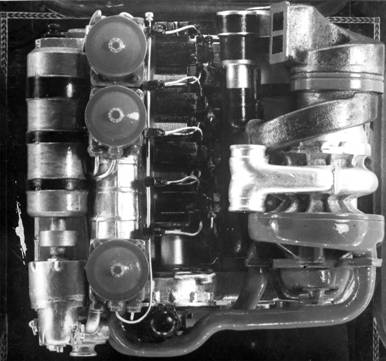
Diesel 4TPD
FIREPOWER, MOBILITY,
AND SURVIVABILITY
The installation of a stabilized 100-mm
gun with a muzzle velocity of 1015 m/s, advanced fire-control and aiming
devices, ammunition stowage of 58 rounds, fuel capacity of
FIRST VARIANT
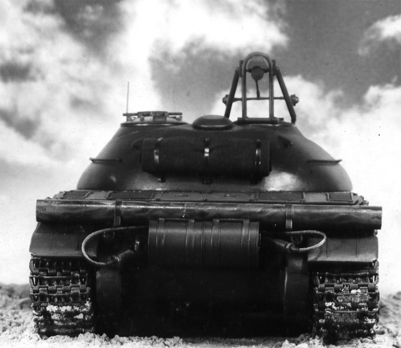
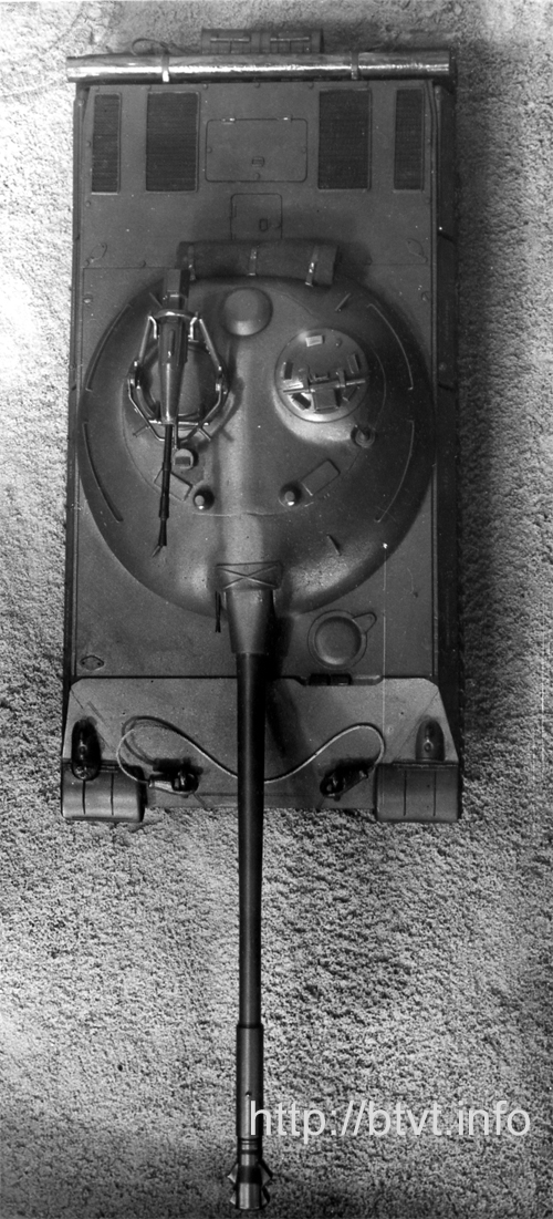
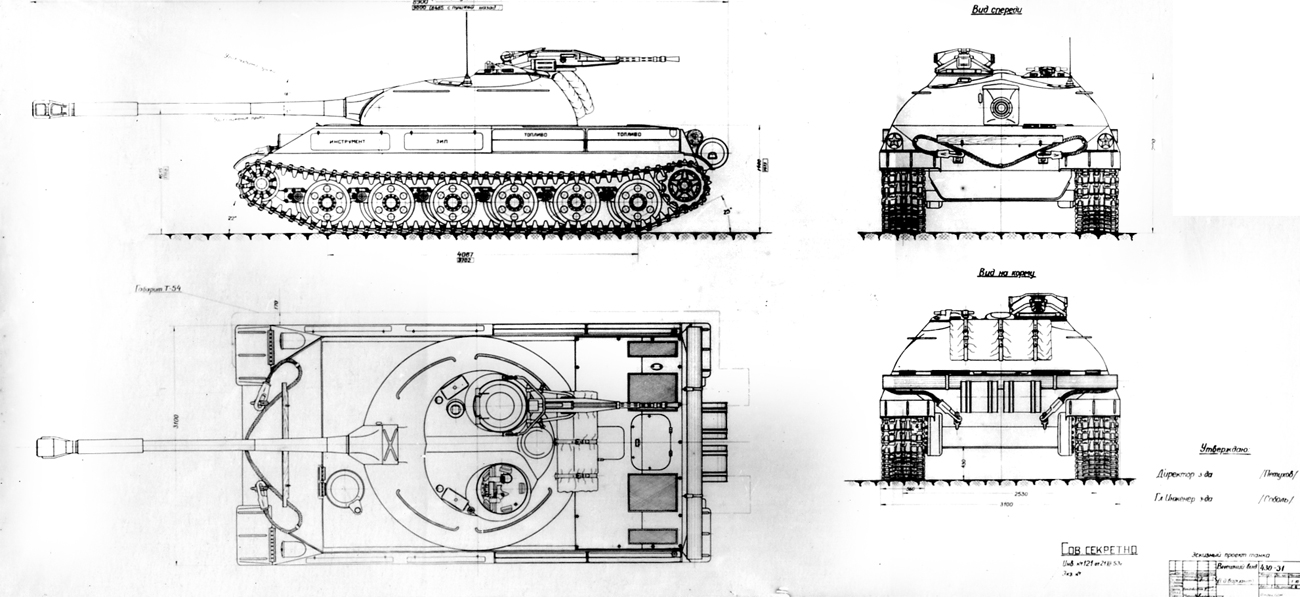
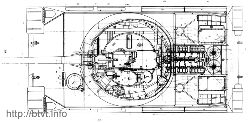
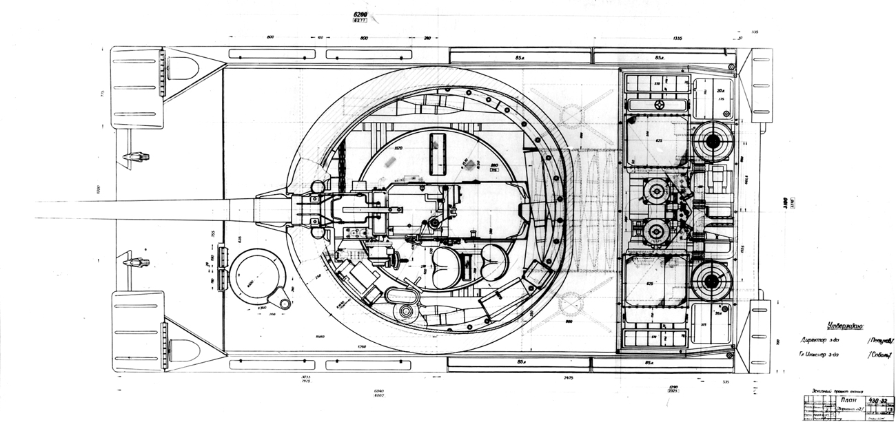
The layout of Object “
Object “
All devices and mechanisms required
for combat operations, as well as the main gun and machine-gun ammunition
stowage, are located in the forward part of the hull.
In the forward hull section, on the right side,
a frontal ammunition rack for 29 rounds is installed, while the driver’s
station is located on the left.
The central part of the vehicle houses the
fighting compartment and turret, which accommodate:
Ammunition in the fighting
compartment is arranged as follows: four rounds are placed in side-wall
recesses (two per side), two rounds are stowed in the turret bustle, and five
rounds are located in the automatic feed magazine mounted on the rotating turret
floor (on the right side of the gun system). The remaining 15 rounds are housed
in wet stowage racks located at the rear of the hull along the right and left
sides.
This ammunition arrangement allows
the loader to simultaneously use both the frontal and rear stowage racks,
thereby increasing the practical rate of fire.
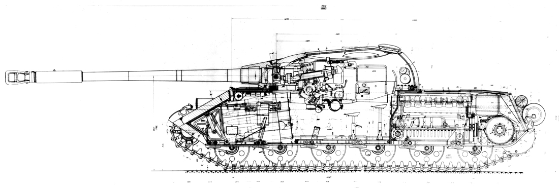
The engine–transmission compartment
is laid out as compactly as possible in order to maximize volume efficiency,
while still ensuring adequate access to units requiring maintenance and servicing,
as well as ease of installation and removal.
The engine is installed longitudinally along
the tank’s axis, with its front end directly coupled to the gearbox.
On the left and right sides of the
engine, adjacent to the fighting compartment and in the lower hull, four
batteries are installed, with free access provided from within the fighting
compartment.
Above the batteries, on both sides
of the engine, two wet ammunition stowage racks are installed, accommodating a
total of 15 rounds and incorporating
Between the ammunition stowage racks
and the transmission, in the lower hull on both the right and left sides, two
auxiliary tanks of
A 260-liter fuel tank is located in
the forward hull section, while an 80-liter oil tank is positioned in the rear.
Additional fuel totaling
The total fuel capacity amounts to
Tank equipment, spare parts, and entrenching
tools are stowed in the side compartments located in the forward sections of
the fenders.
In the engine–transmission
compartment, directly adjacent to the rear armor plate and on both sides of the
engine, ejector boxes are mounted on the transmission units. These represent
compartments sealed off from the engine bay, upon which the radiators are
installed. One of the radiators (the left one) serves as a combined water–oil
radiator.
The air cleaners are located behind the engine,
between the cooling compartments and above the transmission, with free access
provided through a hatch above them.
On the left side of the engine, in the lower
part of the hull, a preheater boiler is installed.
Access to the fuel pump, injectors,
water pump, and oil pump of the engine is provided through inspection hatches
located both in the roof above the engine compartment and in the tank’s bottom.
A description of the design of the
remaining mechanisms and systems of the first variant of Object “
SECOND VARIANT
The layout of Object “
In the second variant, Object “
As in the first variant, all devices and
mechanisms required for combat operations, as well as the ammunition for the
main gun and machine guns, are located in the forward section of the hull.
In the forward hull section, on the right
side, a frontal ammunition rack for 29 rounds is installed, while the driver’s
position is located on the left.
The central part of the vehicle
contains the fighting compartment and the turret, which in this variant is
shifted
The turret and fighting compartment
accommodate:
Ammunition in the fighting
compartment is arranged as follows: 28 rounds are placed in a transverse
stowage rack adjacent to the engine bulkhead; four rounds are housed in
side-wall recesses (two per side); two rounds are located in the turret bustle;
and five rounds are carried in the automatic feed magazine mounted on the
rotating turret floor (on the right side of the gun system).
The total ammunition load of the
tank amounts to 68 rounds.
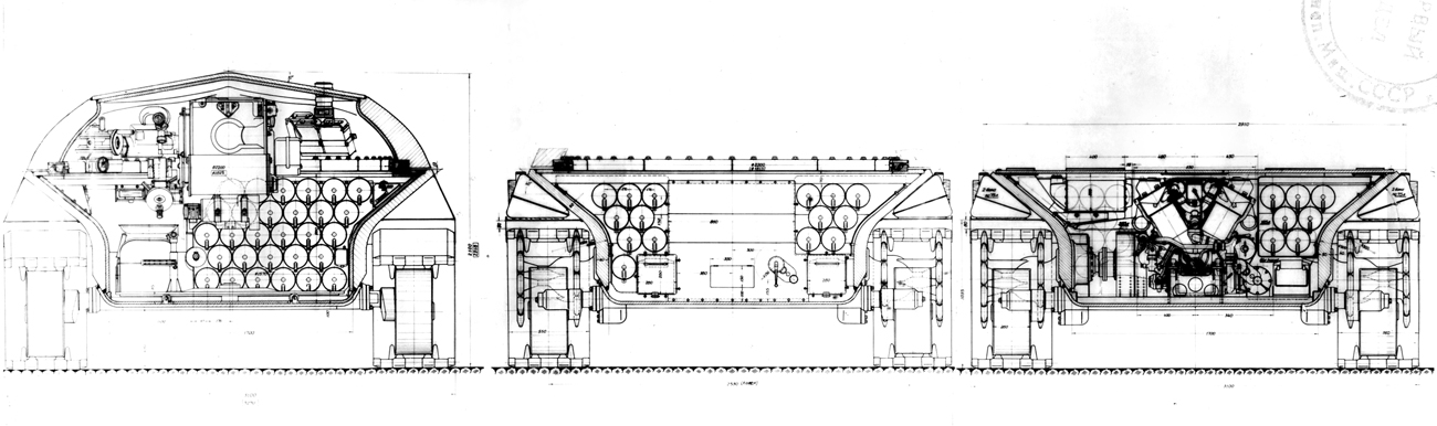
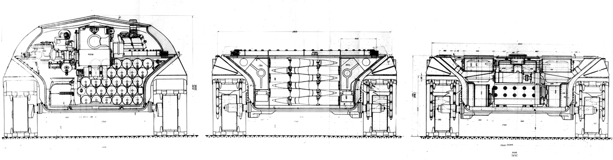
Engine–Transmission
Compartment
The engine–transmission compartment
of the second variant represents a fundamentally new and most advantageous
layout scheme. It is arranged in an extremely compact manner to maximize
internal volume utilization, while ensuring sufficient access to units
requiring maintenance and servicing, as well as complete freedom for the
installation and removal of each unit individually.
The engine is installed transversely.
On both sides of the engine, symmetrically with respect to the tank’s
longitudinal axis, two planetary transmissions are installed, structurally
integrated within a single housing together with the final drives.
At the upper rear, directly adjacent to the
rear armor plate, two air cleaners are mounted on the transmission units.
Behind the air cleaners, at the
engine bulkhead and on both the right and left sides of the engine, ejector
boxes are installed. These boxes form compartments sealed off from the engine
compartment, on which the radiators are mounted. One of the radiators (the left
one) functions as a combined water–oil radiator.
On the right and left sides of the
lower hull, along the transverse ammunition rack, four batteries are
installed—two on each side—arranged sequentially and providing free access from
the fighting compartment.
Above the batteries, two fuel tanks
with a capacity of
A 450-liter fuel tank is located in the forward
hull section, while in the rear section two auxiliary tanks with a total
capacity of
The total fuel capacity is
The oil tank is located in the rear,
directly adjacent to the rear armor plate, and has a capacity of
Access to the engine’s fuel pump,
injectors, water pump, and oil pump is provided through inspection hatches
located both in the roof above the engine compartment and in the tank’s bottom.
Layout Advantages and
Operational Benefits
It should be noted that this type of
engine–transmission compartment layout provides substantial advantages both in
terms of internal volume efficiency and overall weight reduction.
The placement of two transmissions
on either side of the engine—each occupying a volume comparable to that of the
final drives in the T-54—eliminates from the engine–transmission compartment
such units as the reduction gear (“guitar”), main clutch, gearbox with all
associated mounting brackets and foundations, as well as a number of other
assemblies and mechanisms that constitute a significant portion of the volume
and weight of the T-54’s powertrain compartment.
At the same time, the use of non-ferrous
aluminum castings for transmission housings can be completely eliminated, and
the total number of transmission components is reduced, thereby lowering the
manufacturing cost of the tank.
The presence of the two
aforementioned transmissions in the power transmission scheme of Object “
The application of an ejector
cooling system, particularly successfully implemented in the second variant of
the project, eliminates the need for a cooling fan, fan support structure,
separating bulkhead, and fan drive.
The number of semi-rigid connecting
couplings requiring alignment during installation is reduced threefold—from six
in the T-54 to two—thereby reducing assembly labor and directly improving the
tank’s suitability for mass production.
The number of seals on rotating
transmission components—common sources of leakage during operation—is
significantly reduced, from
The number of lubrication points in
the transmission system is reduced to a minimum. Instead of 15 lubrication
points in the T-54, Object “
If, in addition to all the above, it
is taken into account that the air, oil, and fuel filters designed for Object “
A description of the design of the
main mechanisms and systems of the second variant of Object “
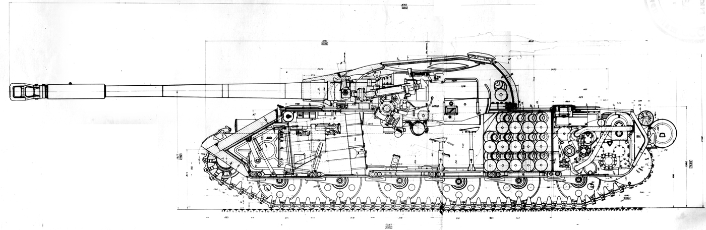
The turret of Object “
In the upper part of the turret, a cast
roof plate
Unlike all existing turrets of
medium tanks, the turret of Object “
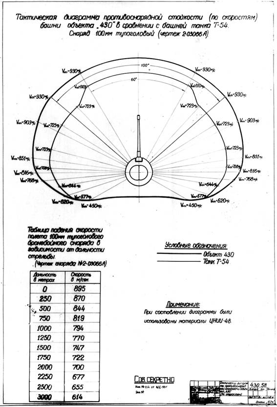
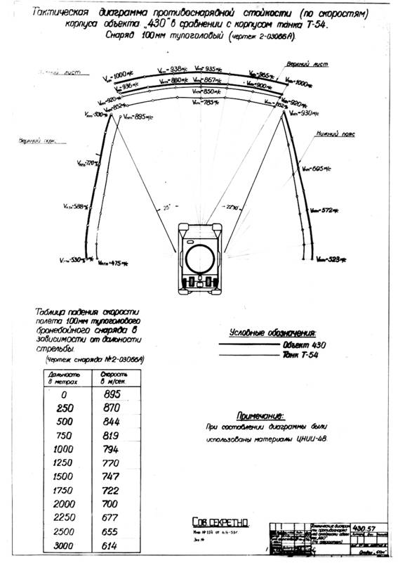
The armor protection of the hull and
turret is designed so as to ensure resistance against 100-mm projectiles at a
velocity of 930 m/s within the following sectors:
The achieved level of armor
protection of the hull and turret is significantly higher than that of the T-54,
and in certain areas even exceeds that of the IS-4 and Object “
As for comparisons between the armor protection
of the hull and turret of Object “
RUNNING GEAR
SUSPENSION
The suspension of Object “
In both the first and second
suspension variants, the elastic element is a torsion bar, with a diameter of
The balancer arm radius (R) in the
first and second variants is adopted as
Road wheel travel in the first
variant is
Through the use of outboard supports
in both suspension variants, it was possible to significantly reduce the load
on the balancer bushings from support reactions in comparison with the
suspension of the T-54, as well as to increase the length of the torsion bar. This
design ensures the above-mentioned dynamic road wheel travel of
Double-acting piston-type hydraulic
shock absorbers, featuring a special conical profile and unloaded seals, are
installed in both the first and second variants on the first and sixth road
wheels. Their design configuration and the curves of their combined performance
characteristics are shown in the figures.
TABLE
Suspension Travel and
Specific Potential Energy
CONCLUSION
The preliminary design study of the
new medium tank has demonstrated that, through a more successful arrangement of
mechanisms and a more advanced design of its assemblies, it is possible to
achieve a significant improvement in the tactical and technical characteristics
of a medium tank, while maintaining its combat weight within the range of 35–35.5
metric tons.
In the present study, this improvement—when
compared with other medium tanks—has been achieved across all principal
parameters defining the combat and technical qualities of the tank as a
fighting vehicle, in many cases reaching levels that exceed the specified
tactical-technical requirements, as well as the existing parameters of the
heavy tanks IS-3, IS-4, and Object “
All of the above indicates that the
combat and technical parameters currently realized in medium tanks are far from
their ultimate limits and may be substantially increased without increasing the
tank’s combat weight.
The principal factors that enabled Plant No. 75
to achieve a positive solution to this task are the fundamental principles
incorporated in the development of the project, namely:
Economy in the use of scarce,
costly, and strategic materials required for tank production.
It may be assumed that the new medium tank
presented in this preliminary design project, in addition to its high tactical
and technical performance, will also meet requirements with respect to manufacturability,
labor intensity, production cost, and service life, as demanded of modern
combat equipment, thereby achieving even greater superiority over the armored
fighting vehicles of foreign armies.
PLANT
DIRECTOR (Petukhov)
COMPARATIVE TACTICAL AND TECHNICAL CHARACTERISTICS OF MEDIUM TANKS
REPORT BY A. A. MOROZOV AT THE MINISTRY REGARDING OBJECT “430” 22 February – 10 March 1954. — Work on the New Medium Tank (NMT) has been carried out by the plant since early 1952. The tactical and technical requirements (TTR) for tank development were submitted by the Scientific and Technical Committee (NTK) of the GBTU to the Ministry of Transport and Heavy Machine Building (MTrM) in mid-1951. Work has continued for three years, and only now have we reached the stage of a preliminary design. During this period, the NMT project was reviewed several times by the MTrM, but not a single decision was taken on it. It should be noted that very little attention has been paid to the NMT program by the GBTU, the MTrM, and cooperating plants. The results presented here were achieved exclusively through the initiative and persistence of the plant’s designers, who have continued to work stubbornly on this subject. The current pace of work cannot be considered satisfactory and lags far behind the pace of work at foreign plants. For example, in the journal Military Thought, No. 1 for 1954, page 49, it is stated: Last year, during the development of the preliminary design, it was found possible to exceed the specified TTR. For three years, the requirements for cruising range, carried ammunition load, protection against toxic agents and dust, crew working conditions, and so forth remained unchanged. All of this was not reflected in the new TTR prepared by the NTK of the GBTU for approval by the Council of Ministers of the USSR. Moreover, there are proposals originating from certain individuals within the GBTU to avoid “getting too far off the ground” and to “prevent unforeseen consequences,” and therefore to seek more moderate solutions, relying on existing engines and assemblies at the expense of reducing the combat and technical characteristics of the NMT achieved in the presented projects. I am opposed to such attitudes and consider them not only incorrect but even harmful, contradicting the directives of our Party and Government to strive for everything new, advanced, and progressive—first and foremost in military technology. In all cases, we are not inclined to “trail behind” foreign technology and will persistently seek opportunities to work on new, although very difficult, directions in special-purpose vehicles. It must be noted that the Americans, in particular, during the postwar period, have carried out extensive work in the field of the NMT, created many designs, and continue to improve them. Numerically, we are producing fewer designs, and this is our shortcoming, despite having all the possibilities to always be ahead. In the presented NMT project, our plant set itself the task of achieving the maximum possible exceedance of the specified TTR and incorporating into the new vehicle everything new that would contribute to improving its combat and technical characteristics. In addition, in this NMT project we attempted to make a sharp break from existing designs, achieving a certain leap similar to that which occurred with the appearance of the T-34. The NMT is a medium tank within the traditional weight class, but with sharply increased tactical and technical characteristics, far surpassing all vehicles known to us. We present three developments: two variants of the tank with 4TD and D12-U engines, and one variant—the reinforced “430U.” The 4TD and D12-U engines have a power output of 580 hp. They occupy the same volume and operate with the same transmission. When installing the D12-U, we obtain: high fuel consumption (170–190), reduced cruising range (a decrease of 10–15%), greater heat transfer to the coolant—195 thousand kcal/hour versus 139 thousand kcal/hour, low exhaust back pressure, the need to increase the water radiator area by 60%, lower gas flow rate—0.48 versus 0.85, and a lower flow of ejected air—3.32 kg/s versus 4.08 kg/s. The vehicle layout is new and original and opens up good prospects for further development. The plant succeeded in significantly exceeding the specified TTR while remaining within the assigned weight. The project is realistic and within the plant’s capabilities. All this makes it possible to sharply increase the combat and tactical qualities of domestic armaments and thereby further strengthen the power of our Soviet Army relative to foreign armies. The achieved parameters are far from being the limit and can be further improved. Hundreds of comments have been worked through, which will be reflected in the detailed design. As part of an initiative effort, a project of a “reinforced” tank in terms of armament and protection is presented, developed on the basis of the “430” and providing for the possibility of further improvement of the NMT. All of this has been achieved through a new layout of the power-train compartment and a new engine. When using an engine of the V-2 type, only part of these characteristics can be obtained; we presented such results in 1953. The disadvantages of using the 8D12-U engine are: greater difficulty in meeting the weight limits, reduced cruising range, high fuel consumption, smaller ammunition load, an engine hood that covers the engine, low back pressure for ejection, large radiator area, large power-train compartment volume, and the absence of a major leap in NMT development. Object “419” will be such a vehicle within a year. We are capable of doing better than what is proposed with the 8D12-U engine. We must not be afraid of a new engine and new directions in the design of mechanisms (gearbox, track, automation). We still have many reserves for improving tactical and technical characteristics, reducing weight, and more efficiently using internal volumes.
|
|||||||||||||||||||||||||||||||||||||||||||||||||||||||||||||||||||||||||||||||||||||||||||||||||||||||||||||||||||||||||||||||||||||||||||||||||||||||||||||||||||||||||||||||||||||||||||||||||||||||||||||||||||||||||||||||||||||||||||||||||||||||||||||||||||||||||||||||||||||||||||||||||||||||||||||||||||||||||||||||||||||||||||||
|
|
||||||||||||||||||||||||||||||||||||||||||||||||||||||||||||||||||||||||||||||||||||||||||||||||||||||||||||||||||||||||||||||||||||||||||||||||||||||||||||||||||||||||||||||||||||||||||||||||||||||||||||||||||||||||||||||||||||||||||||||||||||||||||||||||||||||||||||||||||||||||||||||||||||||||||||||||||||||||||||||||||||||||||||