|
|
|||||||||||||||||||||||||||||||||||||||||||||||||||||||||||||||||||||||||||||||||||||||||||||||||||||||||||||||||||||||||||||||||||||||||||||||||||||||||||||||||||||||||||||||||||||||||||||||||||||||||||||
|
|
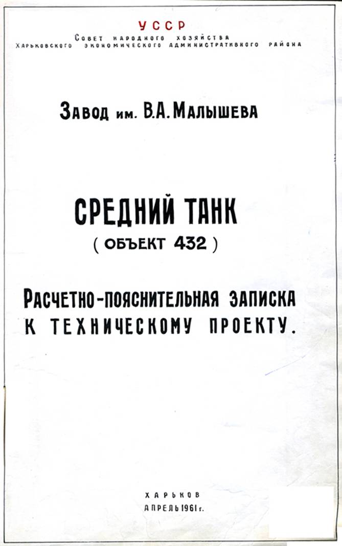
Technical Project “Object
Andrei Tarasenko
Annotation
The article presents a comprehensive
technical and historical analysis of the Technical Project
“Object 432” (April 1961) — the prototype that laid the
foundation for the T‑64, the first Soviet main battle
tank. Particular attention is given to the
evolution of the composite hull and turret protection, the
development of the automatic loading system, and the
implementation of integrated NBC (nuclear, biological, chemical)
defense systems. The research highlights the
technological challenges encountered during early production — such as design
shortcomings of the “cheeked” glacis, turret modifications, and the transition
from fiberglass to multi‑layer steel‑ceramic protection — and
traces their resolution through the evolution of T‑64A/B models.
The analysis demonstrates that Object 432 became a milestone in armored vehicle development, establishing the
architectural and technological framework later used in the T‑72, T‑80, T‑90, and derivative tanks
across the world.
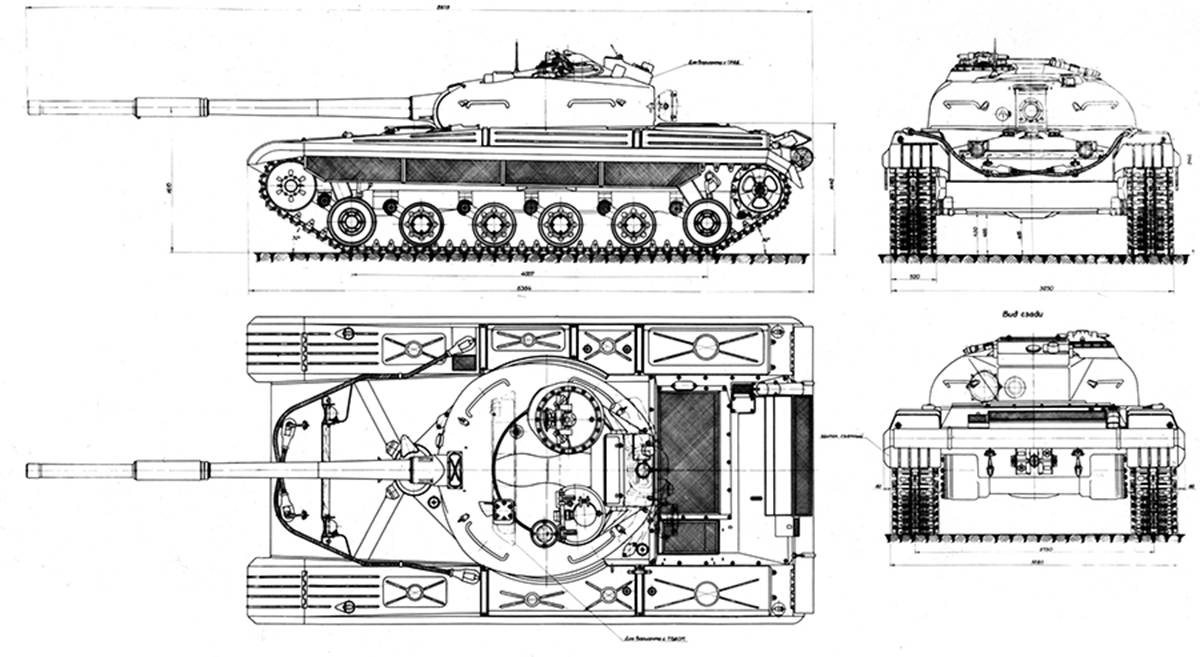
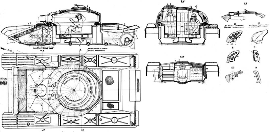
External
views of the “
Development and Design Objectives
At the turn of the 1950s–1960s,
Soviet tank‑building faced the task of developing and putting into series
production, in the shortest possible time, a new main battle tank capable of
operating under conditions involving weapons of mass destruction and
significantly surpassing all existing production tanks in its tactical and
technical characteristics.
On March 15, 1962,
the “
Decree of the USSR Council of
Ministers №693‑291 of July 4, 1962, authorizing
production of a pilot batch of “Object
By 1964, serial
production of the T‑64 tank began according to
documentation prepared under the supervision of chief designer A. A. Morozov.
Although criticized for initiating series production before formal adoption
into service, this step ultimately proved necessary: it enabled broad‑scale
trials and operational testing, which in turn allowed continuous refinement of
the design.
After modifications and repeated
testing, the tank was officially adopted by the Soviet Army under decree №982‑321 of the CPSU Central
Committee and Council of Ministers, dated December 30, 1966,
which also confirmed its principal performance specifications.
Thus began an entire era in Soviet
tank development—one that would determine the evolutionary direction of armored
vehicles for decades to come.
The “
Like any fundamentally new machine,
the T‑64 had to overcome significant difficulties during development and
early deployment, gradually eliminating deficiencies and leading the way for
successors.
The design principles embodied in
the T‑64’s layout continue to live on in the T‑72, T‑80, T‑90, BM “Oplot”, Al‑Khalid, Type 96, Type 99, VT‑1A,
and other derivative tanks—many of which still serve worldwide today.
This article presents the key sections of the design
justification and explanatory memorandum for the technical project of
the medium tank “Object
In several areas that might raise
additional questions, explanatory notes are provided based on quotations and
remarks from A. A. Morozov and other specialists in the field.
By mid‑1961, the technical project for the new tank Object 432 had been approved, establishing unprecedented protection, powerful armament,
and high mobility for its time. The concepts defined in this project set the course
for Soviet tank design for many decades.
Compared with both in‑service Soviet
medium tanks and the experimental “Object 430,” the new technical design
envisioned the following major improvements:
• Increased firepower and fire control efficiency, achieved through installation of a 115 mm smoothbore gun
of the “Molot”
(Hammer) type, equipped with precise sighting systems and a mechanical
loading device ensuring high rate of fire.
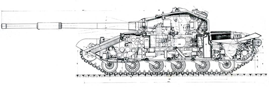
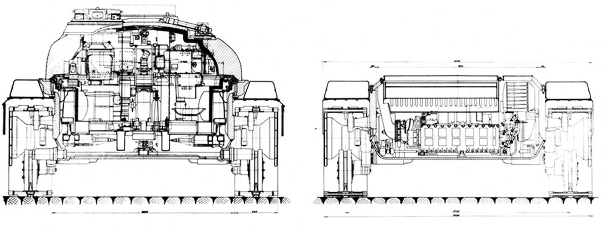
Firepower and Combat Compartment Layout
The general internal layout of the
tank and arrangement of its main compartments remained similar to Object 430,
except for a radically redesigned fighting compartment executed under a new scheme.
To increase firing power, the tank
was equipped with a 115 mm
smoothbore gun D‑68, with an initial armor‑piercing
projectile velocity of 1615 m/s. In addition to AP
shots, the gun fired HE (high‑explosive) and HEAT (shaped‑charge) rounds.
The D‑68 was similar to the U‑5TS
“Molot”
gun but included structural changes required by the new turret
layout—specifically reduced recoil length
(320 mm vs 430 mm), elimination of the folding gun
guard, substitution of the elevation mechanism with a manual hydraulic pump acting
on the stabilizer cylinder, reduced wedge projection, and a 250 kg
overall weight reduction.
The gun was stabilized in
two planes using the “Siren” system, designed specifically for this
project and offering high accuracy.
To improve stabilizer performance,
the turret was inclined 1° forward, allowing the gun to
depress up to 6°3′ relative to the horizon.
The sighting complex included a TPDMS
combined sight‑rangefinder, capable of both stereo and monocular
ranging. Alternatively, the tank could be equipped with a radar
rangefinder (system No. 42 project) integrated with a T2S
sight.
These advanced aiming devices were
expected to greatly enhance firing accuracy; the limiting factor for rate of
aimed fire would be the loading process. Thus, manual loading was deemed unacceptable—it would restrict the high cyclic rate required in
modern combat.
Consequently, the design devoted
special attention to eliminating the loader as a crew member and creating a sophisticated mechanized loading system, capable
of holding 30 rounds (75 % of the onboard load of 40 rounds) in the automatic loader carousel.
This decision significantly improved
both firepower and fighting efficiency while reducing crew size and internal
armored volume, thereby lowering overall tank weight.
When discussing unused armored
volumes in existing tanks, it is worth recalling that in the Object 430,
to allow the loader to operate manually while standing, the entire right‑hand
side of the fighting compartment—over 2 m³, or approximately 18 % of the
tank’s total internal volume—was practically empty.
Therefore, one of the major design
challenges of the new layout was to utilize this previously wasted
space. The problem was solved as follows:
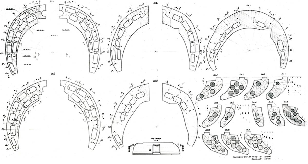
The loading mechanism was
designed for separate‑loading ammunition with a semi‑combustible
cartridge case, whose components were significantly smaller than those
of a unitary round. This made it possible to accommodate the entire automatic
loader system within the hull, arranging the ammunition in a circular
conveyor that defined the shape of the redesigned fighting
compartment—a cylindrical capsule (turret basket) suspended
from the turret ring.
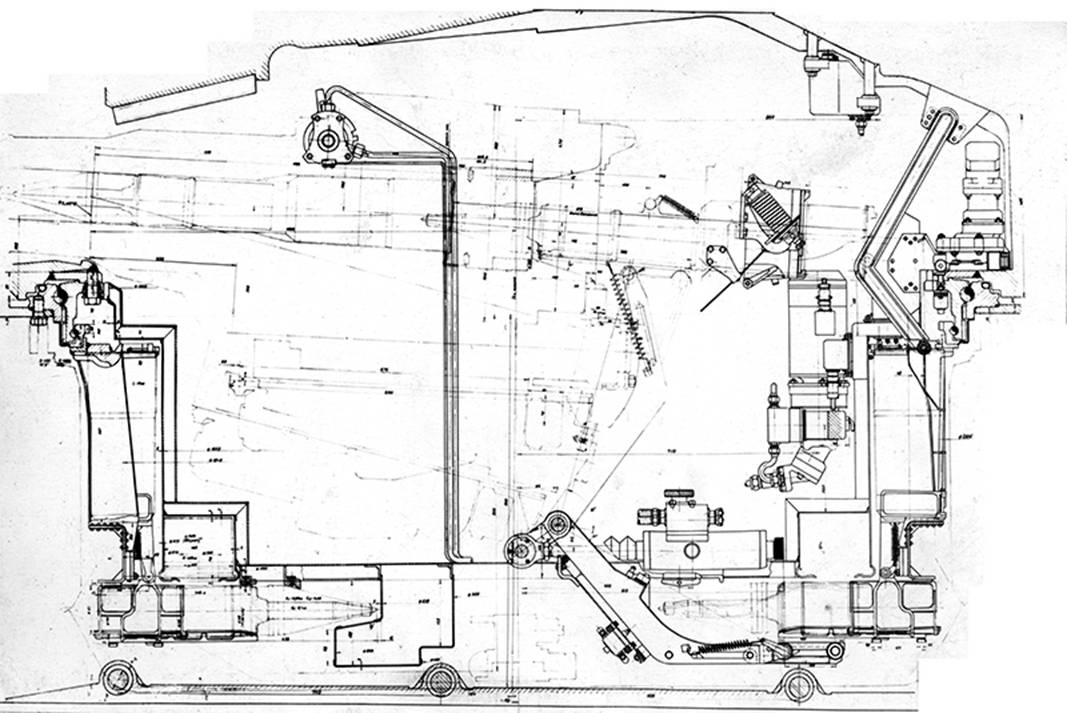
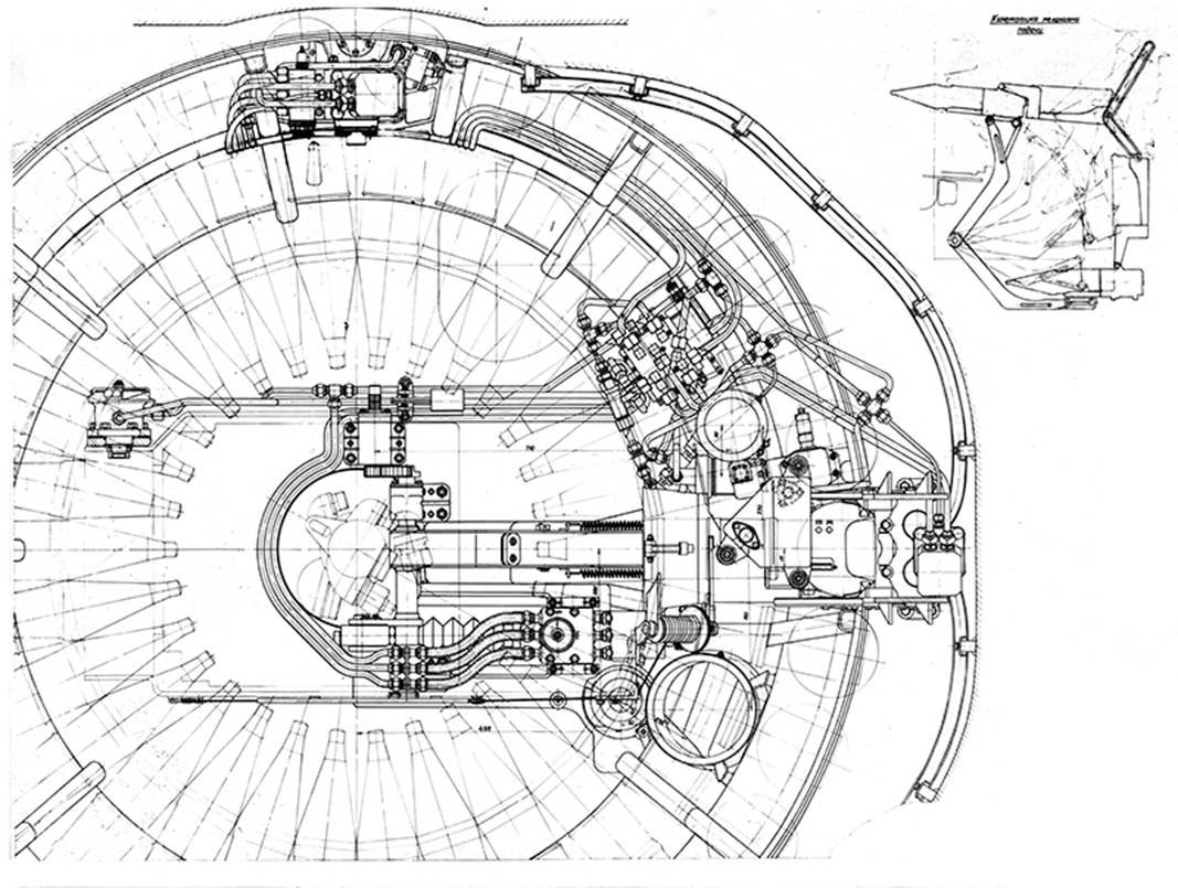
Loading
Mechanism
Loading
Mechanism
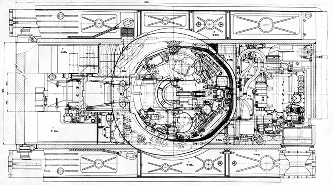
Design of the Automatic Loading Mechanism
The adopted loading mechanism
consisted of a rotating carousel conveyor holding 30
rounds, mounted on an internal ring affixed to the turret ring
bearing. Cartridge cases were positioned
vertically (base upward) in individual cassettes connected to horizontal trays
beneath the floor, which carried the projectiles.
Control of the autoloader was
centralized on a gunner’s control panel with three selector
buttons, each corresponding to a projectile type. Next to the buttons, round
counters indicated the remaining ammunition of each type.
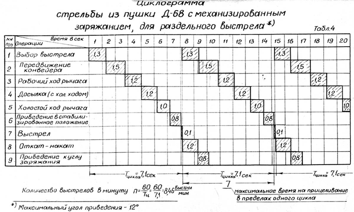
Loading Cycle
Once a type of round was selected,
the loading process proceeded automatically through the following steps:
All actuators were hydraulically
powered by an independent pump unit. The calculated rate of
fire was 8.46 rounds per minute.
Cyclogram of firing from a D-68 cannon with mechanised loading
Spent Case Handling
To prevent the gun muzzle from
striking the ground during reloading (an issue discovered on Object 430),
the gun automatically elevated to +2° for the duration of the
loading cycle. Upon firing, the spent case
base (stub) was ejected into a catcher mounted to the
gun guard. During the next reloading cycle, the catch was flipped by the
loading arm, dumping the stub into a trumpet‑shaped chute that led to a ring collector located at the bottom of the
turret basket. The collector could store 30 cartridge bases,
which were shifted automatically as new ones were added.
The mechanism’s design also included
provision for mechanized replenishment of rounds and cartridge
cases into the conveyor during ammunition resupply.
Crew Arrangement in the Turret
The turret crew consisted of
two men, seated inside the carousel’s central space (inner
diameter ≈ 1650 mm, excluding liner).
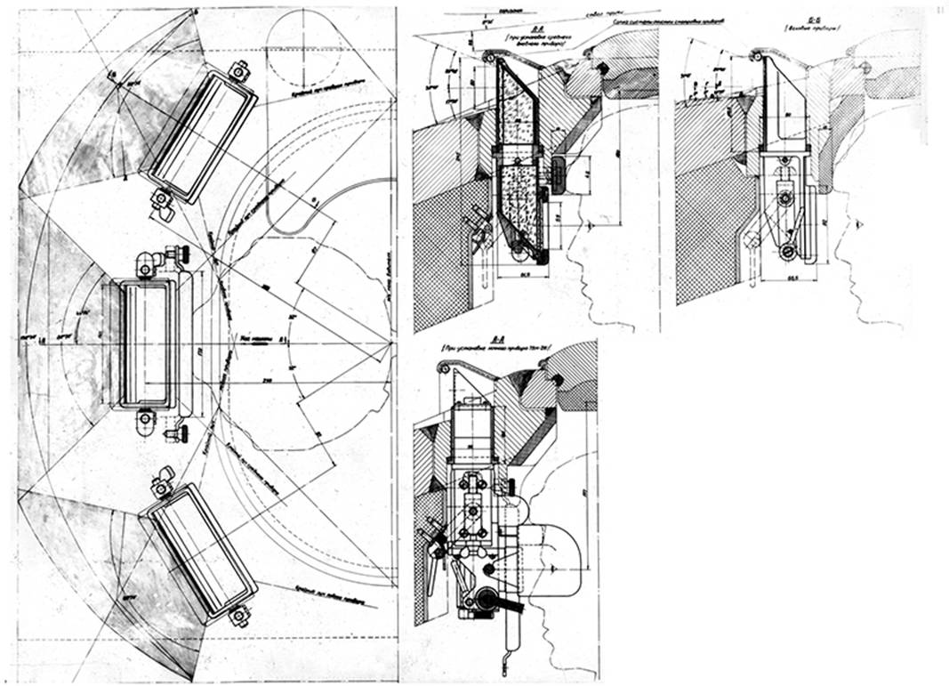
The commander’s station was equipped
with a command cupola containing a central day/night
periscope Karmine‑3 and two flanking daylight vision blocks
identical to the driver’s.
A 7.62 mm coaxial
machine gun of the Nikitin system was mounted parallel to the main gun in front of the commander.
To maximize workspace for the turret
crew, most auxiliary components not requiring direct access were relocated outside
the turret basket. The gunner retained a manual
traverse mechanism with an azimuth indicator, meshing through an internal
gear into the fixed turret‑ring flange.
Ammunition Stowage
Ten reserve rounds were stowed in
the front‑right hull section, inside the front
and rear left fuel tanks. For configurations with a radar
rangefinder, additional specialized equipment had to be installed
inside the fighting compartment. Accessibility and Maintenance
Given the isolated design of the fighting
capsule, the overall internal layout ensured that maintenance of key
systems could be performed from either the driver’s
compartment or the engine‑transmission compartment,
rather than from inside the fighting area.
Compared to Object 430, the
adopted design achieved a saving of over 2 m³ in
internal armored volume.
Design Notes and Technical Analysis
According to the design studies, the specific mass gain due to height increase in a tank is 1.3–1.75 times
greater than an equivalent surface‑area increase caused by
lengthening or widening the hull. Therefore, a reduction in height offers
significant weight savings.
Reducing the internal protected
volume also provides mass efficiency, as the space required for the autoloader
and its ready rounds is considerably smaller than that needed to
accommodate a human loader and his ammunition racks. Effect of Gun Caliber on Firing Rate
The trend toward increased gun
calibers and projectile weights led to the adoption of separate‑loading
ammunition, which unavoidably reduced manual loading speed.
The loader’s physical
capabilities became the limiting factor in achieving higher rates of
fire. Manual loading is the most physically demanding operation in a tank
crew’s combat workflow, performed under cramped conditions with near‑maximum
muscular effort. As fatigue accumulates, the loading cycle lengthens.
For example, simulating the manual
loading of a 125 mm gun (projectile 25 kg, charge 15 kg)
showed that:
Thus, by the tenth round the manual
loading rate had dropped by half.
In contrast, the automatic
loader achieved 8 or more rounds per minute,
maintaining a consistent cycle throughout combat engagements [2].
Entry from A. A. Morozov’s Diary – March 2, 1962
“Today P. I. Barannikov (NII‑21), S. N. Razumovsky, and E. P. Babukhin (NII‑6) arrived regarding the ‘D‑81’
gun. We reviewed two cartridge designs: a unitary round
(mass 39 kg, length 1170 mm) and a separate‑loading
round weighing 32 kg. Colonel Khokhlov stated that the military would not
accept a 40‑kg unitary round for the D‑81.”
Diary Note – April 18, 1961
“We returned again to the question
of future tank armament. We had already discussed this back in June 1958,
then under a wave of enthusiasm for rocket projectiles. Gun artillery was
dismissed as obsolete and ‘dead.’ To keep it from rising again, they set a
requirement for muzzle velocity of 3000 m/s—a target obviously
unattainable—after which the project was shut down. “Thanks to
those who continued work on the ‘Molot’ and ‘Rapira.’ In general, the artillery plants accomplished little; as a result, our armored
forces stagnated, and meanwhile the Americans caught up by developing the M60.
I remember how three years ago everyone made bold promises—shortened deadlines,
built experimental bases, adopted sound decisions—but nearly all rocket
projects were closed. We were left with nothing. There is still no rocket
system capable of competing with the gun.”
“For tank armament, the main
priorities are: high muzzle velocity, long point‑blank range, and high
rate of fire. Tank duels at long ranges should be avoided—that’s the role of
surface‑launched rockets and aviation. The tank is a close‑combat
weapon, and from the ‘Molot’ gun we must extract the maximum
muzzle velocity through new propellants and physical principles.”
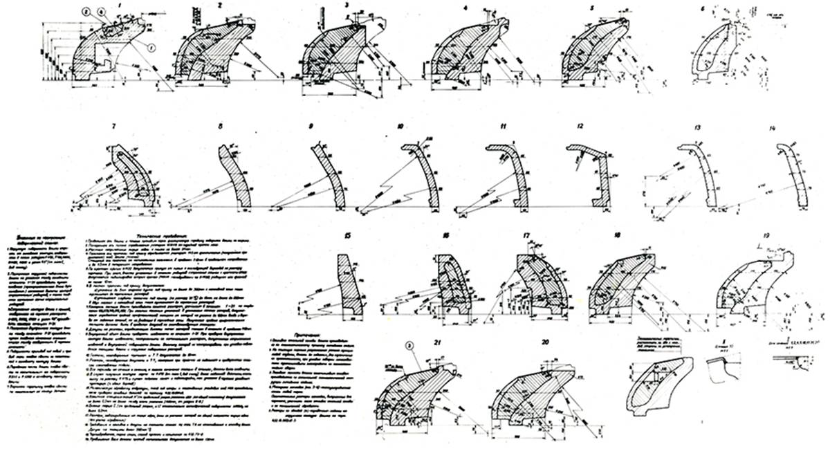
Protection Systems: Armor, Anti‑Cumulative
Structure, and NBC
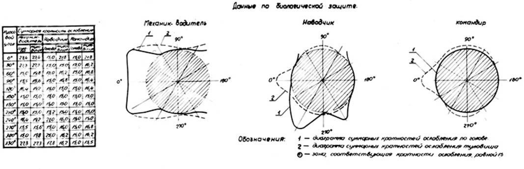
Schematic diagram of the
radiation protection system for tank ‘432’.
General Principles
Diagram of
“Object 432” protection against shaped‑charge and armor‑piercing
projectiles. The growth of tank gun calibers and
projectile velocities, the introduction of sub‑caliber penetrators, and
the widespread use of high‑efficiency HEAT (shaped‑charge)
warheads, coupled with the urgent requirement to provide biological
shielding for the crew from nuclear radiation, dramatically
complicated the problem of developing adequate protection.
To counter all these hazards
simultaneously, the designers abandoned the concept of simple monolithic armor
and introduced a composite, integrated (multi‑layer) protection
system, consisting of:
Depending on surface geometry, slope
angles, and spatial constraints, different combinations of these components
were analyzed. The following arrangements were adopted as optimal.
|
|||||||||||||||||||||||||||||||||||||||||||||||||||||||||||||||||||||||||||||||||||||||||||||||||||||||||||||||||||||||||||||||||||||||||||||||||||||||||||||||||||||||||||||||||||||||||||||||||||||||||||||
Protected area / zone
|
Against kinetic (AP) projectiles
|
Against shaped charge (HEAT)
projectiles
|
Upper front plate (glacis) of the
hull
|
|
|
Turret front – in the 80° sector
|
Equivalent to: ≈
|
Steel plate thickness in the
direction of horizontal jet ≈
|
|
|
|
Turret sides – up to course angle
40°
|
|
|
Projectile defeat is guaranteed
against
|
–
|
–
|
All other elements of armor
protection
|
Not inferior to those of the T-55
tank
|
Not inferior to those of the T-55
tank
|
Biological Protection
|
Against penetrating radiation
from a nuclear explosion of a medium-yield bomb (60 kt)
|
Achieved through the use of:
special liner (подбой) and fiberglass, in combination
with reinforced steel armor protection
|
||
Ensures crew survivability inside
the tank at a distance of 900–1000 m from ground zero, with the following:
|
||||
Dose
|
Attenuation factor
|
|
||
200 rem (or equivalent biological dose)
|
≥ 15 times (reduction by approximately 40–45%)
|
|||
При нахождении на зараженной местности с
уровнем 300 рентген/Час
|
Provides an attenuation
factor of 18 (allowing operation for 12 hours at a total dose of 200
roentgens)
|
|||
When operating on contaminated
terrain with a radiation level of 300 roentgens/hour
|
Under the action of a blast wave
with a front‑pressure of 3.5 kg/cm², the
pressure increase inside the fighting compartment does not exceed 0.35 kg/cm² (a ten‑fold reduction)
|
|||
Prevention of radioactive dust
penetration into the fighting compartment
|
Achieved by creating an overpressure
of 0.003 kg/cm² inside the fighting compartment using a special blower (нагнетательная) unit
|
|||
Air cleaning for air supplied to
the fighting compartment
|
Performed by dust separation in
the blower unit with a cleaning coefficient of 0.99 (99%) for unlimited
operating time
|
|||
Note: Object 432 became
the first production tank equipped with composite armor protection for both the hull and turret.
Naturally, the introduction of this new concept was not without initial problems.
The design of the upper
glacis with “cheeks” (angled side extensions) proved unsuccessful.
From the diaries of A. A. Morozov:
22 December 1965 — Radus‑Zenkovich: “The ‘cheeks’ do not protect
the tank against shaped‑charge projectiles. They must be removed.”
26 February 1966 — “…The ‘cheeks’ cause
turret jamming; they must be eliminated.”
As a result, additional
deflector‑shields (“eyebrows”) were installed on the cheek areas
to prevent ricocheting projectiles from striking the joint between the hull and
turret.
Later, the “cheeks” were entirely removed, and the hull glacis
was replaced by a flat plate design.
At the same time, the driver’s three periscopic vision blocks were replaced with a single wide‑format
periscope.
The original armor configuration described in the technical project — 80 mm
steel + 140 mm fiberglass laminate — was later
replaced by a modified layout, consisting of:
- rear backing plate 20 mm steel,
- 80 mm steel outer plate + 105 mm STB
(fiberglass) + 20 mm steel
inner backing.
A solid
fin‑stabilized projectile, when penetrating fiberglass
laminate, does not fracture or deform in the same way
as it does when striking steel armor.
Tests of three‑layer barriers (steel + fiberglass + steel)
showed a sharp increase in resistance:
the increment of equivalent protective thickness (Δυₚₖₚ) per unit of added material was 2–3 times
greater than that achieved by simply increasing the thickness of a
homogeneous steel plate.
Therefore, under equal weight
conditions, a three‑layer barrier exceeds a single‑layer
steel plate in protection efficiency.
This occurs because the rear steel plate is impacted by a deformed
projectile, partially destroyed after passing through the first steel
layer, having lost both velocity and the original shape of its nose portion.
In multi‑layer structures, the fiberglass’s resistance to penetration
rises sharply due to the additional steel backing support [3].
In serial production, the T‑64 adopted the second turret variant, with an aluminum anti‑shaped‑charge
filler.
This production turret had a considerable overall thickness—about 600 mm—which
reduced the crew’s internal working space.
(From A. A. Morozov’s diary: “The tank commander becomes fatigued and has no space to use a map.”)
The refinement of the ultra‑porcelain‑insert
turret (later using spherical inserts) was delayed.
By the start of serial production of Object 434,
manufacturing continued with a turret containing inserts of high‑hardness
steel.
It was later replaced by a turret with corundum balls (introduced
on 1 January 1974), which became the standard for
the T‑64A and T‑64B main
production series until completion [4].
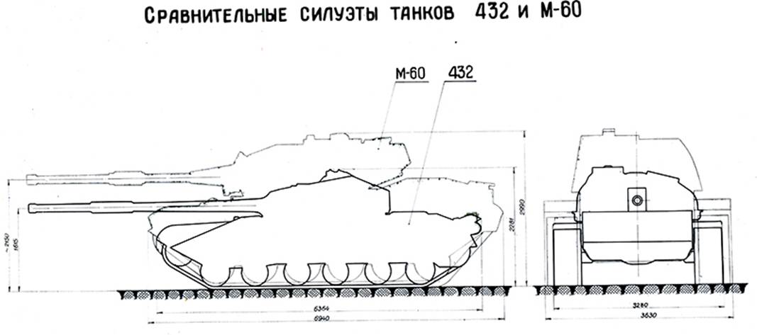
До появления современных систем управления огнем небольшая
лобовая проекция играла важнейшую роль в защите танка.
References
- Tanks and People. Diary of the Chief
Designer A. A. Morozov / compiled by V. L. Chernyshev. –
- Influence of Gun‑Loading Automation
on the Overall Properties of the Tank. Vestnik of Armored Vehicle Engineering, No. 1, 1981.
- On Certain Regularities Determining the
Protective Properties of Three‑Layer Barriers under Fire from Solid
Fin‑Stabilized APDS Projectiles. O. I. Alekseyev, Cand. of Tech. Sci., I. I. Terekhin. Issues of Defense Technology, Series XX, Issue 63, 1976.
- Improvement of Tank Turret Manufacturing
Technology. L. T. Ilinkova, M. G. Kovriga, G. A. Chikalenko. Vestnik of Armored Vehicle Engineering, No. 2, 1982.
- Main
| ГЛАВНАЯ | НА ВООРУЖЕНИИ | ПЕРСПЕКТИВНЫЕ РАЗРАБОТКИ |
ОГНЕВАЯ МОЩЬ ЗАЩИТА ПОДВИЖНОСТЬ |
ЭКСКЛЮЗИВНЫЕ МАТЕРИАЛЫ | БИБЛИОТЕКА | ФОТООБЗОРЫ |